Tag: networking

  • Road to CCNP: Day 108 (BGP)

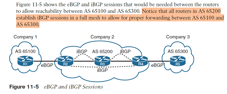
    3.2.c Configure and verify eBGP between directly connected neighbors (best path selection algorithm and neighbor relationships)

    Two routers can form a BGP peering relationship if they have working IP reachability to each other and the BGP session parameters match.

    1. Create the eBGP process
      1. Router bgp [process-id]
    2. Statically assign routing ID
      1. Bgp router-id [router-id]First choice is any up loopbac
      1. Then any up interface
    3. Identify the link’s neighbor
      1. Neighbor [ip] remote-AS [remote-AS #]
      1. Applies to both internal BGP and external BGP, meaning even if the neighbor is within your own AS you still have to use the command
    4. Define the network to advertise (much like rip or ospf)
      1. Network [network address] mask [subnet mask]
      1. Means if I have an interface that’s UP within this network and mask, I want that interface and its network to be advertised in this routing protocol
    5. Initialize address family with command
      1. (router-config-bgp)# address-family []
    6. Activate for the neighbor with
      1. neighbor [ip-address] activate

    Multiprotocol BGP = MBGP = allows IPv4 and IPv6 to coexist on the same device and routes are not shared, with the same BGP process

    Verification of BGP

    • show ip bgp summary = came out before multiprotocol
    • show bgp [ipv4/ipv6] summary

    BGP Session States
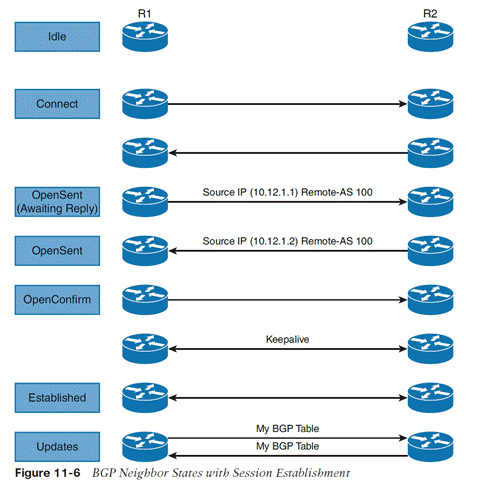
    1. IDLE = sitting there doing nothing
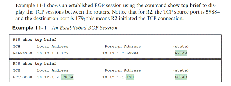
    2. Connect = each side initiates TCP connections with each other using TCP port 179. Three-way handshake Routers always listen on port 179 for connection requests but the source port is ephemeral. That means the first router to initiate the connection is the one with source port random high number.
    3. Active = first connection is open and active. BGP starts a second TCP connection and keeps it open for 4 minutes. The next step is OpenSent, which remains until the timer reaches 0.
    4. OpenSent = R1 sends an Open message to R2. Upon receipt, R2 will send an Open message back. Once both routers receive an open message, they do CRC check and check BGP configurations, which must match. Open messages contain info about the source router configuration.
      1. BGP versions must matchSource IP address of Open msg
      2. must match that of the neighbor commandRID’s must be exist and be unique.
      3. must match that of the neighbor commandAS number in the Open msg.
    5. OpenConfirm = If the Open messages have no errors, a KEEPALIVE is sent and the hold timer is reset and status enters OpenConfirm.
    6. Established = Upon each router receiving a KEEPALIVE, they enter Established. BGP session is initiated. Route information is exchanged in the Update message type. KEEPALIVES are sent to keep Established open.

  • Road to CCNP: Day 107 (OSPFv2, OSPFv3)

    3.2.b Configure simple OSPFv2/v3 environments, including multiple normal areas, summarization, and filtering (neighbor adjacency, point-to-point, and broadcast network types, and passive-interface)

    OSPF sends neighbor routers a Link-state advertisement (LSA). Inside the LSA is the link state and metric. Received LSAs are stored in a local database called the LSDB, and a router that receives an LSA floods it out through other links, just as it was received. This process continues until all routers have the same LSDB and picture of the entire network. Then, each router runs Dijkstra’s algorithm (shortest path first/SPF) with itself as the top of the tree.

    This gives the illusion to the router that there is no redundancy. But if a link goes down, the SPF will be recalculated, with the redundancy now in effect.

    Scalability = multiple areas are allowed.

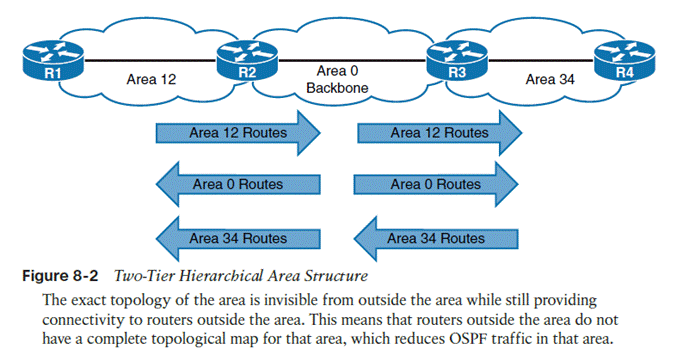
    Should not exceed 50 routers per area. Must have area 0, or a backbone. All non-backbone areas must have an area border router (ABR) with the backbone. Non-backbone ABRs advertise/inject routes into the backbone, which backbone routers flood amongst themselves until they have the same LSDB, and then backbone ABRs then inject non-backbone routes into other non-backbone areas.

    Don’t Interrupt 2 Engineers Exchanging Large Files

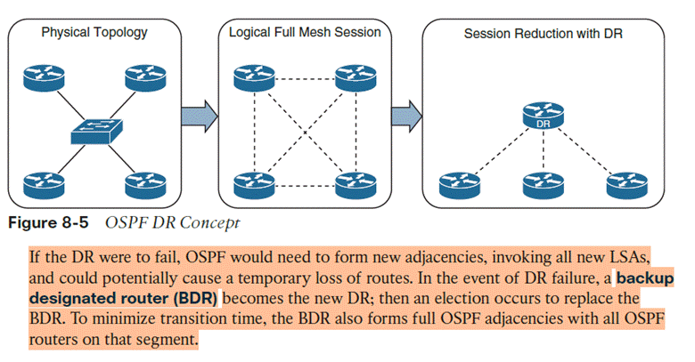
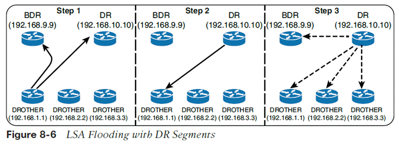
    The DR/BDR process distributes LSAs in the following manner, assuming that all OSPF routers (DR, BDR, and DROTHER

    1. As an OSPF router learns of a new route, it sends the updated LSA to the AllDRouters (224.0.0.6) address, which only the DR and BDR accept and process
    2. The DR sends a unicast acknowledgment to the router that sent the initial LSA update
    3. The DR floods the LSA to all the routers on the segment via the AllSPFRouters

    OSPFv3 configuration

    1. First enable IPv6 unicast routing as OSPFv3 messages communicate over IPv6 links
      1. Command ipv6 unicast-routing
      1. Router ospfv3 [process-id]
    2. Define the router ID.
      1. If the router is IPv6 only, then a router-id must be manually assigned. In addition, if the router has no interfaces with IPv4 addresses, a router-id cannot be automatically assigned
      1. Use a manually configured router-id if one exists.
      1. Otherwise, choose the highest IPv4 address on a loopback interface.
      1. If there is no loopback, choose the highest IPv4 address on an active non-loopback interface.
      1. If there are no IPv4 addresses at all, OSPFv3 cannot dynamically pick a RID and effectively has 0.0.0.0; adjacencies won’t form.
      1. Command router-id [router-id]
    3. Enable OSPFv3 on an interface
      1. Command ospfv3 [process-id] ipv6 area [area #]
    4. OSPFv3 does not use the network statement for initializing interfaces.

    Passive interfaces

    • Command passive-interface [interface-id]
    • Passive-interface default
      • Enable per interface with no passive-interface [interface]

    Show commands

    show ip ospfOSPF process, RID, areas, SPF info, reference bandwidth
    show ip ospf neighborNeighbor adjacencies and states
    show ip ospf neighbor detail Detailed neighbor information
    show ip ospf interface brief  Quick view of OSPF-enabled interfaces
    show ip ospf interface  Full interface OSPF parameters
    show ip ospf interface g0/0          OSPF information for one interface
    show ip ospf databaseContents of the LSDB
    show ip route ospf OSPF routes installed in the routing table
    show ip protocols    Routing protocol configuration/parameters

    Summarization to sum up multiple addresses in one routing table entry

    Area [area-id] range [prefix/prefix-length]

    Network types

    OSPFv3 supports the same network types as v2, Broadcast, point-to-point, loopback

    To configure per interface, ospfv3 network [point-to-point/broadcast]

    IPv4 support in OSPFv3

    1. Ensure the IPv4 interface has an IPv6 address because OSPFv3 communication occurs over IPv6 and the router needs a link-local address to talk to neighbors
    2. Enable OSPFv3 on the IPv4 interface with command ospfv3 [process-id] ipv4 area [area-id]

  • Road to CCNP: Day 106

    3.2     Layer 3

                                  3.2.a          Compare routing concepts of EIGRP and OSPF (advanced distance vector vs. link

    state, load balancing, path selection, path operations, metrics, and area types)

    EIGRP diffusing update algorithm (DUAL)

    • Successor route = the best EIGRP path to a destination
    • Successor = the next-first hop on the best path
    • Feasible distance = The lowest EIGRP distance metric of the best route (“it is feasible that the best route is x”)
    • Reported distance = the neighbor’s own metric to a destination
    • Feasibility condition = Neighbor RD < current FD
      • Passes → path is guaranteed loop-free and can be a feasible successor.
      • Fails → EIGRP cannot guarantee from the FC alone that it is loop-free. It does not mean a loop definitely exists.
    • Feasible successor = Route that satisfies the feasibility condition (guaranteed loop-free) and therefore can be hot-swapped to in case the successor route goes down

    Topology table = contains all the network prefixes advertises in an AS

    • Network prefix
    • Neighbors that have that prefix
    • Metric from each neighbor
    • Values used to calculate the FD

    Neighbors advertise the entire routing table when forming an adjacency, and only advertise changes

    Message types

    • 1. Update = respond to requests, transmit routing and reachability info to neighbors
    • 2. Request = ask neighbors to get specific info
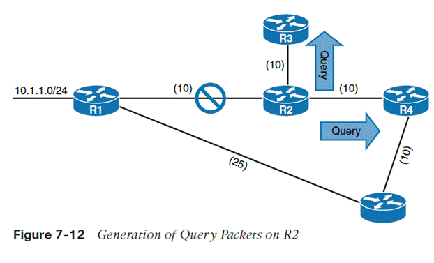
    • 3. Query = sent to search other paths during convergence
    • 4. Reply = sent in response to query
    • 5. Hello = discovery of EIGRP neighbors (absence of hello also detects unavailability)

    Metric Calculation

    • Bandwidth and delay
    • Interface load and reliability

    Load balancing

    Multiple paths to the same network prefix is ECMP = MULTI PATH

    Successor route and feasible successor can be installed at the same time and used to forward traffic, this is unequal cost load balancing

    Variance multiplier is a value

    Variance value = multiplier * feasible distance

    Any feasible successor whose FD is lower than this variance value can also be installed in the routing information base and be used to route traffic, up to a max amount of routes

    Traffic share count is ratio of traffic sent across each path

    Hello packets, heartbeat to neighbors, hello timer, interval of heartbeat, 5 second default, 60 on T1 interf.

    Hold time, time for EIGRP to hold out for for hello packets from neighbor

    Default hold time is 3 x hello timer, eg. 5 hello timer = 15 sec hold time, 60×3 = 180 sec on T1 interf or lower

    Receiving hello packet restarts hold time, when hold time reaches 0 the neighbor is deemed unreachable and notifies DUAL of topology change

    Convergence

    When an EIGRP node goes down, every link attached to that node goes down too. Anywhere where that node was part of the route (ie a successor or upstream router), path recomputation must occur

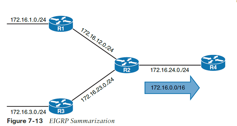
    Summarization

    When enabled, component routes are not advertised, and only the summary route is advertised.

    It is only advertised when a request for a component network is requested

    Configured on a per-interface basis

  • Road to CCNP: Day 105

    3.3.c Configure first hop redundancy protocols, such as HSRP, VRRP

    FHRP use Virtual Ips (VIPs)

    • Hot Standby Router Protocol (HSRP, one VIP, two routers, failover), active standby
    • Virtual Router Redundancy protocol (VRRP, one VIP, two routers, constant probing of other router, failover when other router fails to respond in time), master backup
      • HSRP is cisco proprietary, VRRP is open
    • Gateway Load balancing protocol (GLBP, multiple routers, traffic can be round-robined to different routers, or statically assign a flow to a specific router)

    HSRP Config

    1. Define instance with standby [instance-id] ip [virtual IP address of gateway]
    2. (optional) enable preemption with standby [instance-id] preempt
    3. (optional) change default priority with standby [instance-id] priority [priority #]
    4. (optional) change HSRP mac address in case of network migrations with standby [instance-id] mac-address [mac address]
    5. (optional) change the HSRP timer with standby [instance-id] timers [seconds | miliseconds]
    6. (optional) enable HSRP authentication with standby [instance-id] authentication [text password]
    7. View HSRP status with show standby [instance-id] [brief]

    Why object tracking is needed: it’s needed because of R1 doesn’t actually go down but its link does, object tracking can detect the link down state and decrease R1’s priority so that R2 can preempt it

    Track [object #] interface [interface #] OR track [object#] ip route [route/prefix] reachability
    Standby [instance-id] track [object-id] decrement [decrement value]

    Virtual Router Redundancy Protocol (VRRP)

    • Uses master/backup instead of active/standby
    • Preemption enabled by default
    • Commands start with vrrp instead of standby
    • Mac address structure 0000.5e00.01xx where xx is VRRP group ID in hex (remember openstandard = advanced, 5e)
    • Uses 224.0.0.18 for communication
    • VRRPv2 is Ipv4 only, VRRPv3 supports IPv4 and IPv6
    1. vrrp [instance id] ip [VIP address]
    2. (optional) change priority with vrrp [instance-id] priority [priority #] 1-255
    3. (optional) enable object tracking to change priority when object is down vrrp [instance-id] track [object-id] decrement [decrement value]
    4. (optional) enable VRRP authentication with vrrp [instance-id] authentication [password]

    Hierarchical VRRP in VRRPv3

    Like an ACL, you create the instance and then issue commands in the config modeo f that instance

    1. Enable VRRPv3 with fhrp version vrrp v3
    2. Define the instance with vrrp [instance-id] address-family [Ipv4 | Ipv6]
    3. (optional) enable compatibility with command vrrpv2
    4. In config mode, define the gateway VIP with command address [ip-address]
    5. (optional) change priority with command priority [priority #]
    6. (optional) enable object tracking with command track [object-id] decrement [decrement-value]

    Gateway Load Balancing Protocol (GLBP) = provides the redundancy of HSRPs and a load-balancing capability

    so basically different hosts use the same VIP for gateway, get assigned different routers by the AVG, and use different MAC addresses for the ARP mapping of their default gateway

    1. Define GLBP instance with command glbp [instance-id] ip [VIP address]
    2. (optional) configure preemption on the preferred router with command glbp [instance-id] preempt
    3. (optional) change priority with command glbp [instance-id] priority [#] 1-255
    4. (optional) change timers with command glbp [instance-id] timers [hello seconds] [hold seconds]
    5. (optional) enable authentication with command glbp [instance-id] authentication [password]

    GLBP weighting types

    • Round robin
    • Weighted = assign weights to each device to define the ratio of load balancing
    • Host dependent = map a HOST MAC address to a virtual forwarder MAC
  • Road to CCNP: Day 104

    3.3 IP Services

                                  3.3.a     Interpret network time protocol configurations such as NTP and PTP

    R1(config)# ntp master [#] = tell R1 to become an NTP server of # stratum

    R2(config)# ntp server [ip address] = tell R2 to become an NTP client of [server ip address]

    R2(config)# ntp server [ip address] source [loopback int] = use the loopback’s IP as source for NTP packets, because the loopback address is stable and doesn’t change

    R1# show ntp status = show very verbose info about the NTP process on the device

    R2# show ntp associations = preferred way to check, shows NTP clients and servers

    If multiple NTP servers are setup on a device, device will prefer the lowest stratum

    R1(config)# ntp peer [R2], R2(config)# ntp peer [R1]

    NTP peering = two devices can set to peer each other, the device will take the time from the peer that is most accurate

    • Stratum — generally, a lower stratum is preferred.
    • Reachability — the source must actually be responding reliably.
    • Offset — how far the device’s clock differs from that source.
    • Delay — network delay to the source.
    • Dispersion/jitter — how stable/accurate the source appears over time.

    PTP (https://standards.ieee.org/ieee/1588/4355/), when a few miliseconds of drift is not good enough

    • Grandfather clock is designated, best clock in the domain
    • All other devices synchronize to it
    • PTP accounts for processing delay, travel time, propagation delay (time it takes to put packets on the link)
    • Devices exchange timing messages to calculate this delay as the PTP packet passes through them, lets them know downstream and downstream can correct their time to compensate

    Grandmaster = best clock in domain

    Ordinary clock = a PTP endpoint, i.e. a device syncing their own clock to max accuracy for operations

    Boundary clock = sync to grandmaster, and serves downstream devices

    Transparent clock = as PTP packets inevitbaly pass through intermediate devices, transparent clocks perform PTP calculations and send downstream to boundary/ordinary clocks

  • Road to CCNP: Day 102

    %       4.0         Network Assurance


    4.1                  Diagnose network problems using such as debugs, conditional debugs, traceroute, ping,

    SNMP, and syslog

    Ping, traceroute, debug command, make access lists to filter better, undebug all command to remove all, syslog


    4.2       Configure and verify Flexible NetFlow

    Capture statistics on who talked to who, how they did, and how much

    Statistics available per host

    Conf t, ip flow-export version #, flow-export destination [IP]

    Navigate to interface, ip flow egress, ip flow egress

    Show ip flow interface, export, show ip cache flow, ip flow-top-talkers (why the hyphen LOL>??)

    WHO talked to WHO, HOW, and HOW MUCH


      4.3        Configure SPAN/RSPAN/ERSPAN

    Same switch, SPAN = Switched Port Analyzer, connect to and configure the switch to duplicate the traffic to another interface

     Remote different switch, RSPAN = Remote Switched Port Analyzer, remote switch sends traffic back to local switch, same layer 2 domain, basically source and destination ports can be on different switches. Send RSPAN traffic over RSPAN vlan. On source switch, Source is interface, destination is remote vlan [number]. Reverse is true for the destination switch.

    Make sure you hit the “remote-span” command on vlan configuration mode

    Remote different device ERSPAN = Encapsulated Remote Switched Port Analyzer, remote device captures and then encapsulates using GRE back to the local network

    Switch(config)# monitor session [number] source interface [interfaces
    Switch(config)# monitor session [ number] destination interface [interface SPAN device is connected to]
    switch#Show monitor session [number]  

                   4.4       Configure and verify IPSLA

    Service provider SLA tracking only provides SLA information within their network. You can use Cisco IPSLA to measure end-to-end SLA. Works as a constant steady stream of ICMP pings (or HTTP messages, if configured that way), measuring specific stats

    • Delay (round trip and one way)
    • Jitter (per direction)
    • Packet loss (per direction)
    • Packet sequencing (fragmented packets arriving in order?)
    • Path
    • Connectivity (per direction)
    • website download time
    • voice quality scores

    5.4       Describe the components of network security design

                                  5.4.a     Threat defense

                                  5.4.b    Endpoint security

                                  5.4.c     Next-generation firewall

                                  5.4.d    TrustSec and MACsec

    Trustsec= apply rules by security group – devices and users are joined to groups, and these groups are used to make policies (eg guest cannot connect to anything NOT guest)

    MACsec aka 802.1AE = layer 2 traffic is only encrypted as it travels, and not in the switch. This allows inspection of the payload itself inside the switch

    Downlink MACsec = encryption of layer 2 traffic between an endpoint and a switch (requires both devices to be MACsec capable. Devices can be configured with ISE or manually per port

    Uplink MACsec = encryption of layer 2 traffic between switches