3.2.b Configure simple OSPFv2/v3 environments, including multiple normal areas, summarization, and filtering (neighbor adjacency, point-to-point, and broadcast network types, and passive-interface)
OSPF sends neighbor routers a Link-state advertisement (LSA). Inside the LSA is the link state and metric. Received LSAs are stored in a local database called the LSDB, and a router that receives an LSA floods it out through other links, just as it was received. This process continues until all routers have the same LSDB and picture of the entire network. Then, each router runs Dijkstra’s algorithm (shortest path first/SPF) with itself as the top of the tree.

This gives the illusion to the router that there is no redundancy. But if a link goes down, the SPF will be recalculated, with the redundancy now in effect.
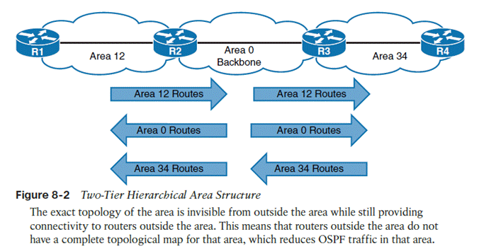
Scalability = multiple areas are allowed.
Should not exceed 50 routers per area. Must have area 0, or a backbone. All non-backbone areas must have an area border router (ABR) with the backbone. Non-backbone ABRs advertise/inject routes into the backbone, which backbone routers flood amongst themselves until they have the same LSDB, and then backbone ABRs then inject non-backbone routes into other non-backbone areas.
Don’t Interrupt 2 Engineers Exchanging Large Files
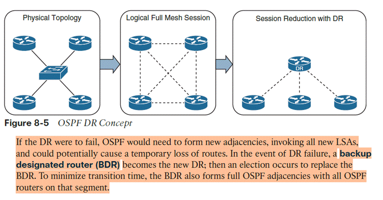
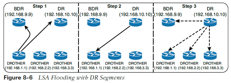
The DR/BDR process distributes LSAs in the following manner, assuming that all OSPF routers (DR, BDR, and DROTHER
- As an OSPF router learns of a new route, it sends the updated LSA to the AllDRouters (224.0.0.6) address, which only the DR and BDR accept and process
- The DR sends a unicast acknowledgment to the router that sent the initial LSA update
- The DR floods the LSA to all the routers on the segment via the AllSPFRouters
OSPFv3 configuration
- First enable IPv6 unicast routing as OSPFv3 messages communicate over IPv6 links
- Command ipv6 unicast-routing
- Router ospfv3 [process-id]
- Define the router ID.
- If the router is IPv6 only, then a router-id must be manually assigned. In addition, if the router has no interfaces with IPv4 addresses, a router-id cannot be automatically assigned
- Use a manually configured router-id if one exists.
- Otherwise, choose the highest IPv4 address on a loopback interface.
- If there is no loopback, choose the highest IPv4 address on an active non-loopback interface.
- If there are no IPv4 addresses at all, OSPFv3 cannot dynamically pick a RID and effectively has 0.0.0.0; adjacencies won’t form.
- Command router-id [router-id]
- Enable OSPFv3 on an interface
- Command ospfv3 [process-id] ipv6 area [area #]
- OSPFv3 does not use the network statement for initializing interfaces.
Passive interfaces
- Command passive-interface [interface-id]
- Passive-interface default
- Enable per interface with no passive-interface [interface]
Show commands
| show ip ospf | OSPF process, RID, areas, SPF info, reference bandwidth |
| show ip ospf neighbor | Neighbor adjacencies and states |
| show ip ospf neighbor detail | Detailed neighbor information |
| show ip ospf interface brief | Quick view of OSPF-enabled interfaces |
| show ip ospf interface | Full interface OSPF parameters |
| show ip ospf interface g0/0 | OSPF information for one interface |
| show ip ospf database | Contents of the LSDB |
| show ip route ospf | OSPF routes installed in the routing table |
| show ip protocols | Routing protocol configuration/parameters |
Summarization to sum up multiple addresses in one routing table entry
Area [area-id] range [prefix/prefix-length]
Network types
OSPFv3 supports the same network types as v2, Broadcast, point-to-point, loopback
To configure per interface, ospfv3 network [point-to-point/broadcast]
IPv4 support in OSPFv3
- Ensure the IPv4 interface has an IPv6 address because OSPFv3 communication occurs over IPv6 and the router needs a link-local address to talk to neighbors
- Enable OSPFv3 on the IPv4 interface with command ospfv3 [process-id] ipv4 area [area-id]